How to Choose the Right Timing Pulleys?
Choosing the right Timing Pulleys is a precision decision, not a catalogue exercise. The pulley must match the belt profile, tooth pitch, width, speed, torque, and shaft arrangement. A mismatch can create tooth jumping, vibration, edge wear, or premature belt failure. Sometimes, the smallest error becomes the loudest problem.
Industry data supports careful selection. Grand View Research estimates that the global timing belt market reached approximately USD 7.4 billion in 2022, with continued growth expected through 2030. MarketsandMarkets also identifies automotive automation, robotics, and industrial machinery as major demand areas. These reports describe belts more broadly than pulleys, so their figures should not be treated as direct pulley-market values. That distinction matters.
Robert L. Mott, author of Machine Elements in Mechanical Design, offers a useful engineering principle: “A component must be selected as part of a system, not in isolation.” This principle applies directly to Timing Pulleys. A 20-tooth pulley may fit the shaft, yet still produce excessive speed or insufficient torque. A larger pulley may reduce bending stress, but it also changes center distance and package size. Check the bore, keyway, flange design, material, and allowable speed. Confirm the belt’s minimum pulley diameter. Do not rely on appearance alone.
Good selection begins with real operating conditions. Record load cycles, ambient temperature, contamination, installation space, and maintenance access. Then compare manufacturer drawings, load tables, and traceable specifications. Even experienced engineers can overlook alignment. That is why final verification should include tooth engagement, shaft parallelism, tension, and guarding. Mistakes are possible. Careful measurement makes them less expensive.
Define Pulley Profiles: HTD 3M, 5M, 8M, 14M and ISO 5296
How to Choose the Right Timing Pulleys?
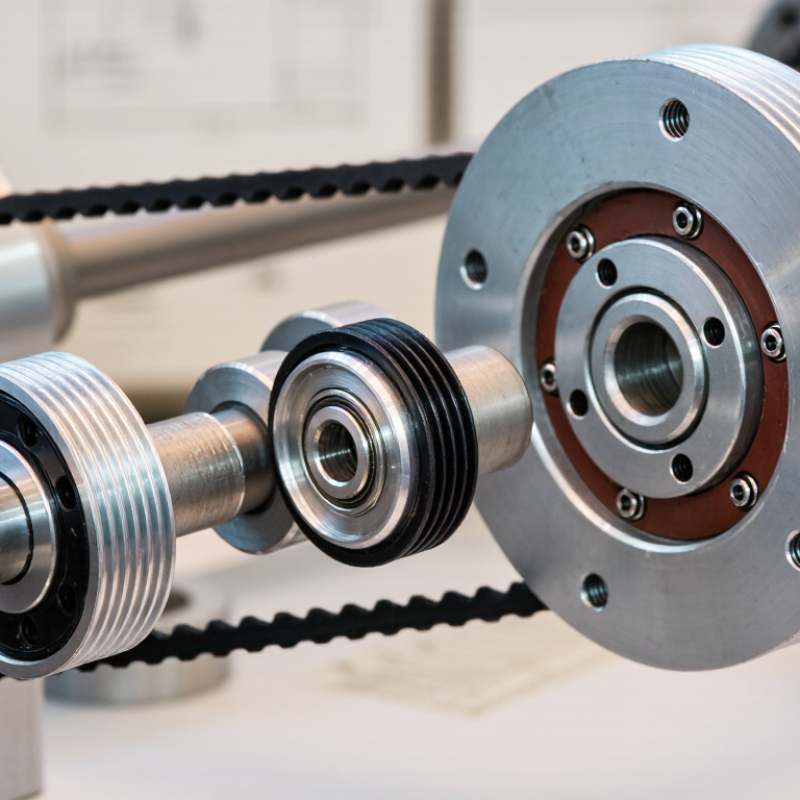
Choosing a timing pulley starts with its tooth profile, not appearance. HTD profiles use rounded teeth for smoother force transfer and reduced stress concentration. The “M” value indicates pitch in millimeters: 3M has a 3 mm pitch, while 5M, 8M, and 14M increase progressively. Smaller pitches suit compact mechanisms and precise motion. Larger pitches usually handle higher torque and wider belts.
HTD 3M works well in small positioning systems with limited loads. HTD 5M is a practical choice for moderate speed and torque. HTD 8M supports heavier drives, including conveyors and industrial actuators. HTD 14M is intended for demanding, high-torque applications where pulley size and belt width are acceptable. Bigger is not automatically better. It can add inertia, noise, and cost.
Use ISO 5296 as a dimensional reference when checking timing-belt drive compatibility, tooth geometry, and pulley sizing. Confirm pitch, tooth count, belt width, bore, and flange requirements together. The pitch diameter can be estimated from tooth count and pitch, using d = z × p ÷ π. In a past selection, I focused only on torque and overlooked the motor’s rapid acceleration. That shortcut caused unnecessary belt vibration. Recheck the real duty cycle, especially during starts and stops. Measure the shaft and inspect alignment carefully. Small errors become visible at high speed.
Match Belt Pitch and Width Using 5, 8, 14, and 20 mm Options
How to Choose the Right Timing Pulleys?
Choosing a timing pulley starts with the belt pitch. The pitch is the distance between neighboring teeth, measured along the belt’s pitch line. Common options include 5, 8, 14, and 20 mm. A 5 mm pitch suits compact mechanisms and lighter loads. An 8 mm pitch often balances space and torque. Larger 14 and 20 mm pitches support stronger drives, but they require more room.
Match the pulley pitch exactly to the belt pitch. Even a small mismatch can cause tooth interference, vibration, or rapid wear. Then check the belt width. A wider belt can transmit more load, but the pulley must provide enough face width for stable tooth engagement. Verify bore size, shaft fit, keyway details, and the required tooth count. More teeth usually improve smoothness, while fewer teeth create a smaller drive diameter. I once focused too heavily on torque and overlooked installation space. That mistake made the final assembly unnecessarily difficult.
Tips: Confirm the pitch before ordering. Measure the belt width with calipers. Check the pulley’s effective width, not only its outside width. For noisy systems, inspect alignment and tension before changing pulley size. Also consider temperature, speed, and shock loads. Calculations help, but real conditions can disagree. Test the selected combination at low speed, then inspect tooth contact and belt tracking.
How to Choose the Right Timing Pulleys? - Match Belt Pitch and Width Using 5, 8, 14, and 20 mm Options
| Belt Pitch |
Typical Designation |
Example Nominal Belt Widths |
Typical Use Range |
Example Pulley Tooth Count |
Calculated Pitch Diameter |
Selection Notes |
| 5 mm |
5M timing belt profile |
9 mm, 15 mm, 25 mm |
Compact drives, light conveying, small positioning mechanisms |
20 teeth |
31.83 mm |
Choose when space is limited and the transmitted load is relatively low. Confirm that the selected belt width meets the required tensile load. |
| 8 mm |
8M timing belt profile |
20 mm, 30 mm, 50 mm |
General industrial drives, conveyors, automation equipment |
24 teeth |
61.12 mm |
A practical middle-size option for balancing compact pulley diameter, load capacity, and availability of belt widths. |
| 14 mm |
14M timing belt profile |
40 mm, 55 mm, 85 mm, 115 mm |
High-torque drives, large conveyors, heavy automation systems |
28 teeth |
124.14 mm |
Use for higher torque and larger center distances. Check shaft size, pulley inertia, flange clearance, and belt tooth-load capacity. |
| 20 mm |
20M timing belt profile |
50 mm, 75 mm, 100 mm, 150 mm |
Very high-torque transmission, heavy machinery, large material-handling systems |
30 teeth |
190.99 mm |
Select for substantial torque and power requirements. The larger pitch normally requires more installation space and stronger shafts. |
Key Matching Rules:
The pulley tooth pitch must exactly match the belt tooth pitch and profile. The pulley belt width should be equal to the belt width specified for the drive; never mix widths or profiles. For a selected pulley, the pitch diameter can be estimated using
Pitch Diameter = Belt Pitch × Number of Teeth ÷ π.
The listed belt widths are common nominal options for preliminary selection, but exact availability and allowable load ratings vary by belt construction and profile.
Verify Torque, Speed, and Service Factors with Manufacturer Data
How to Choose the Right Timing Pulleys?
Choosing a timing pulley starts with verified operating data, not guesswork.
Check the required torque at startup, during acceleration, and under normal load. A pulley that survives steady operation may fail during repeated starts. Calculate the design torque by applying the correct service factor. Use the manufacturer’s published values for tooth capacity, allowable speed, bore limits, and belt compatibility. Do not rely on a similar-looking catalog image.
Speed also deserves careful attention.
Confirm the pulley’s maximum recommended rpm and compare it with the actual shaft speed. Consider vibration, temperature, shock loading, and daily operating hours. Manufacturer tables often separate continuous duty from intermittent duty. That difference matters. I have seen calculations appear accurate while ignoring short overloads. A spreadsheet can look precise and still hide weak assumptions.
Tips:
Record the real load profile before selecting a pulley. Ask the manufacturer to review torque, speed, and service-factor calculations. Check keyways, clamping methods, and alignment tolerances in the same review. If the application is dusty or poorly aligned, increase caution rather than simply choosing a larger pulley. Document every assumption, including motor inertia and start frequency. Some field conditions remain uncertain, and that uncertainty should influence the final selection.
Select Materials, Flanges, Bore Types, and Tolerances for the Application
How to Choose the Right Timing Pulleys?
Choosing a timing pulley begins with the working environment, not appearance.
Aluminum suits lightweight systems and resists general corrosion. Steel handles higher loads, shock, and repeated starts. Stainless steel may be better around moisture, but it often costs more and weighs more. Material selection is rarely perfect. I have seen lightweight pulleys used in dusty, high-torque equipment, where premature tooth wear followed.
Flanges keep the belt aligned, especially on vertical drives or systems with side movement. However, excessive flange contact can damage the belt edge. Choose a pilot bore, finished bore, or taper-lock style according to the shaft and service needs. A finished bore with a keyway supports secure torque transfer. A pilot bore offers flexibility, but machining must be accurate.
Tips:
Check shaft diameter, key size, belt width, and available clearance before ordering. Measure twice. Small errors matter.
Tolerance deserves equal attention.
Bore runout, tooth concentricity, and face alignment influence noise, vibration, and belt life. Tight tolerances help precision motion, but they may increase cost and machining time. For general conveying, extreme precision may add little value. For indexing equipment, it can prevent positioning errors. Document the actual operating speed, torque, temperature, and contamination level. Guessing these details is convenient, but unreliable. A pulley that fits today may not survive tomorrow’s duty cycle.