Leave Your Message
Choosing a Taper Lock Gear is not just a matter of matching teeth and price. Shaft size, transmitted load, operating speed, and available installation space all affect performance. A gear that fits the drawing may still be poorly suited to a dusty conveyor or a frequently serviced drive.
Taper-lock hubs use a tapered bushing to secure the component to a shaft. This arrangement can simplify installation and replacement, but only when the bore, keyway, and tightening procedure match the manufacturer’s specifications. Small details matter. A mismatched keyway or uneven tightening can contribute to movement, wear, or difficult removal. Check the product data sheet, not just the product photo.
This guide compares seven options for industrial buyers, considering construction, compatibility, application range, and practical service needs. Some listings may describe sprockets or related drive components rather than gears in the strict engineering sense; terminology varies between suppliers. That distinction deserves attention before ordering. Buyers should also confirm tooth form, material, bore dimensions, and any required operating factors with a qualified supplier or engineer.
There is no universal winner. A compact unit may suit a light-duty assembly, while a heavier component may be more appropriate for repeated starts or higher loads. Yet a larger part is not automatically better. The shortlist offers a useful starting point, though final selection still depends on the actual drive and working conditions.
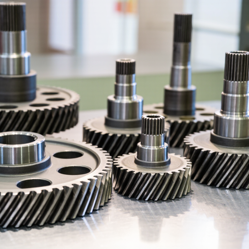
A taper lock gear combines a toothed wheel with a split, tapered bush that grips a shaft. As the bush is drawn into the gear’s tapered bore, it contracts around the shaft. This creates a secure connection without requiring a keyed hub to be machined for every shaft size. Installation still needs care: clean contact surfaces, align the gear, and tighten the fasteners evenly to the specified torque. Small errors can cause runout or vibration.
These gears are used in conveyors, packaging lines, agricultural equipment, and other machinery that transmits rotary motion. For example, a maintenance technician may replace a worn conveyor gear by loosening the bush and fitting a compatible assembly, rather than removing the entire shaft. That can reduce downtime. It is not a magic fix. The gear’s bore, tooth form, load capacity, and shaft dimensions must match the application. Dust, shock loads, and frequent starts also affect service life. In practice, buyers should check operating speed and alignment, then inspect the connection periodically; a loose fit can damage both the shaft and the gear.
| Type | What It Is | Common Industrial Uses | Typical Advantages | Key Selection Considerations | Taper-Lock Fit |
|---|---|---|---|---|---|
| Spur gear | A cylindrical gear with straight teeth parallel to its axis; typically transmits motion between parallel shafts. | Conveyors, mixers, packaging machinery, and general-purpose gear drives. | Simple geometry, straightforward installation, and generally efficient operation. | Check tooth module or diametral pitch, tooth count, pressure angle, face width, material, and required torque. | Suitable when the gear hub is designed for a compatible taper bush and shaft size. |
| Helical gear | A cylindrical gear with teeth cut at an angle to the axis; commonly used between parallel shafts. | Industrial gearboxes, compressors, conveyors, and machinery requiring smooth power transmission. | Gradual tooth engagement can provide smoother and quieter running than a comparable spur arrangement. | Account for axial thrust, lubrication, helix angle, speed, load, and the matching gear geometry. | Can use a taper bush if the gear has a correctly designed, compatible hub. |
| Bevel gear | A gear with a conical pitch surface that transmits motion between intersecting shafts, often at right angles. | Right-angle drives, machine tools, handling equipment, and vehicle differentials. | Changes the direction of rotation between intersecting shaft axes in a compact arrangement. | Confirm shaft angle, gear ratio, tooth form, mounting distance, and matched-pair requirements. | Possible where the hub and available installation space accommodate the selected taper bush. |
| Worm wheel | The toothed wheel that meshes with a worm to form a worm-gear drive, usually with shafts at right angles. | Lifting equipment, conveyors, indexing drives, and compact speed-reduction systems. | Can provide substantial speed reduction in a compact arrangement; some designs resist back-driving, depending on geometry and conditions. | Evaluate ratio, heat generation, lubrication, efficiency, duty cycle, and whether the application needs a separate brake. | A taper bush may be used if the wheel hub is designed for that mounting system. |
| Chain sprocket | A toothed wheel that engages a roller chain; it is a chain-drive component rather than a meshing gear. | Conveyors, agricultural machinery, material handling, and industrial chain drives. | Provides positive, nonslip transmission when correctly matched to the chain. | Match chain pitch, roller diameter, strand count, tooth count, alignment, and lubrication needs. | Taper-bushed sprockets are commonly used for removable shaft mounting; verify bush and sprocket compatibility. |
| Timing-belt pulley | A toothed pulley that engages a synchronous belt; it is a belt-drive component, not a gear. | Automation, positioning equipment, packaging machinery, and synchronized drives. | Toothed engagement helps maintain a fixed speed relationship without belt slip under suitable operating conditions. | Match belt pitch and profile, tooth count, belt width, center distance, tension, and load capacity. | Taper-bushed versions are available in industrial drive systems; confirm the required belt profile and mounting dimensions. |
| V-belt pulley | A grooved pulley that transmits power through friction with one or more V-belts; it is not a gear. | Fans, pumps, compressors, and general industrial belt drives. | A familiar, flexible drive arrangement that can absorb some vibration and accommodate practical center distances. | Select the belt section, groove count, pulley diameter, speed ratio, belt length, and tensioning method. | Taper-bushed pulleys are commonly used where quick installation or removal from a shaft is beneficial. |
What is a taper-lock gear? The term generally refers to a gear or other rotating drive component mounted on a shaft using a matching tapered bush. Tightening the specified screws draws the bush into the component’s tapered bore, securing it to the shaft. Always verify the component, bush, shaft diameter, key, torque rating, and installation instructions as a compatible set. Chain sprockets and belt pulleys are included above as related taper-bushed drive components; they are not gears.